
History and Track Plan – Construction – Control (This Page) – Scenery
The ‘Original’ Burton Crumpnold – How it is wired and controlled
Overview
The Original Burton Crumpnold Baseboard was constructed in 2 sections. This meant that track power and point control has to be fed independently to the left and right sides. I decided against using linking cables between the boards so that all connections could be made at the front using 25 way plug/sockets.
The upper section being connected to the back of the left board probably using a 25 way plug/socket.
The layout has been built for DC use as I basically wanted build the sort of layout I wanted to build when I was young but did not have the space or mostly money.
However, I can now really appreciate the advantages of going DCC in terms of track wiring…
So I made a point of making the layout easily upgradeable to DCC in the future if required
Power
The Original Burton Crumpnold ‘main’ configurations is a DC layout using 4 controllers using common return wiring
(4 power feeds and 1 return).
I used a GaugeMaster DS controller with Simulator Controls for the Outer and Inner Loops.
(The simulator controls do add to the fun as they add a lag on acceleration and deceleration)
An old H&M Duette was used for the Upper Station Branch and the Sidings / Turntables.
Power Control
The Power control of Burton Crumpnold makes extensive use of ‘Cab Control’, this is where sections of the layout can be turned on or off allowing for far more complex movements around the layout.
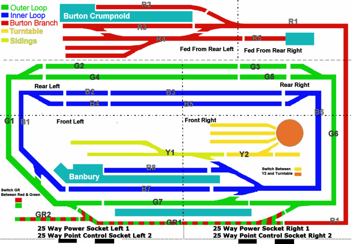
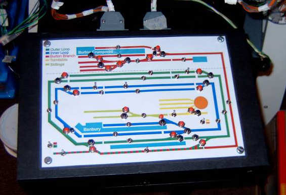
Schematics of the layout showing the main power areas and ‘Cab Control’ isolated sections are shown below.
The Power is divided into 4 sections:
- Green – Outer Oval – Sections G1 to G7
- Blue – Inner Oval – Sections B1 to B8
- Yellow – Inner Sidings/Turntable, Sections Y1,Y2 and YT
- Red – Branch station Loop, Sections R1 to R5.
All Isolated sections are are controlled by micro toggle switches (DPDT).
The sections marked B2, B4 , G3 & G5 are isolated tracks for stopping the ‘out of sight’ trains in the hidden loops.
The sections in GR1 and GR2 can be switched to be powered from the Green (outer loop) or the Red (branch) sections.
A switch on the control panel will allow the power from the ‘yellow’ circuit to be fed to the turntable to control the rotation.
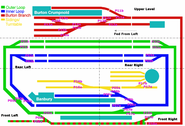
Point Control
Burton Crumpnold uses Hornby Point motors, which are very similar to the peco version. The points are controlled by micro push button switches. The supply to the point switches is fed from a Gaugemaster Capacitor Discharge Unit (CDU) to protect the motors and to allow more than one point to be fired from a button press.
Most of the points on the main board were screwed to the bottom of the baseboard using the extension pins supplied with the point motors. In 2 locations the point was above a cross brace so I was forced to use the Hornby above board solution that uses a little hut to house the point motor.
It is only now all the point control is in place do any weaknesses come out…
… I wired 2 sets of points together on the station passing loop at P06 and P10 (see below). This was done to simplify the wiring and to ensure the the points for the outer loop and the passing loop were properly interlocked. Unfortunately it also severly restricts the length of a train that can be held on the loop as a train goes through the station. I am not sure if I would wire them differently if I could start again – but the restriction is a nuisance..
The following diagram shows the point control.
Main Board Wiring
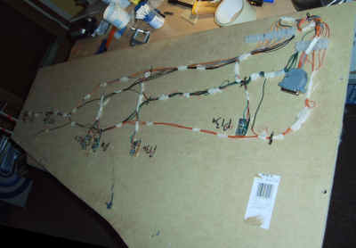
To simplify the wiring I divided the lower board in to 4 sections – 2 for each ‘half board’ – Front Left, Rear Left, Front Right, Rear Right.
Each section was wired to 2 local connector blocks, one for power and the other for point control. These connector blocks were then wired through to ‘Master’connector blocks at the front of the board which were connected to the main 25 way plugs and sockets.
The advantage of this approach was that the wiring could be planned in advance and the main power feeds could be applied to the 4 sections in advance and the section could be wired as required.
All of the wiring for the layout was planned in advance using a spreadsheet and the advance planning meant almost everything worked first time, and what problems were found were easily and quickly fixed.
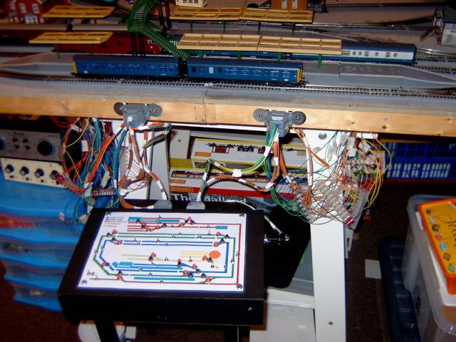
The photograph above shows front ‘Master connector blocks’ before they were tidied up and ‘hid’ in the main board section
Upper Station Wiring
The upper station section was connected up via the Rear left and Rear right connecting blocks via a 25 and 9 way ‘D’ type plugs.
As I am limited in clearance for the trains running underneath I could not mount the points under the board as I have done for the rest of the layout so they are mounted directly on the points.
When I wired the layout’s lower area I connected up all the power and point control feeds to a ‘chocolate block’ connector at the rear of the layout. I was pleased to find that every thing worked when I connected everything up.
To keep the cables flush to the bottom of the board I used a combination of clips and a ‘glue’ gun.
To keep things tidy and to make sure there would be no damage to the cables from the hot glue I wrapped the cables in masking tape and applied the hot glue to the tape.
As I only have a height of 90mm to play with I was concerned that the protruding pins on the points might be a hazard to the underneath trains but a careful test showed all was well.
The Control Panel
The control panel was built into a A4 boxfile. The laminated layout diagram fitted to the top with holes drilled to fit the switches.
The Control panel connects into the layout using 4 25 way plugs, Left Power, Left Points, Right Power and Right Controls. A 9 way plug connects the panel to the power supplies. This makes the control panel portable so it can be easily changed to a new unit.
When I move towards DCC all I need to do is build a control panel with point control with all the power feeds connected together.
Tidying Up
Once all of the power and point wiring was tested the cabling was tidied into small ‘ropes’ using tape and hardboard panels fitted to the bottom of the baseboard frame to protect the cable and connectors
Go onto how the Original Burton Crumpnold Scenery Detail was added