
History and Track Plan – Construction – Control (This Page) – Scenery
Wiring and Controlling Stowey Green
Overview
The Layout is on a single board and will be wired for DC using classic ‘Cab Control’.
.. Athough I plan to use digital control (DCC) in my OO gauge layouts I am quite happy to stick to the simplicity of DC for this layout.
Everything will be powered using a Gaugemaster 2 track controller using common return wiring (2 power feeds and 1 return).
The Gaugemaster controller has Simulator Controls which should add some fun to the layout operation.
The Layout Power and Point control will be connected to the board using two 25way D Type plugs/sockets. One will carry the power, the other the point signals.
These cables will plug into the a Control Panel unit.
Underneath the board there are 4 x 12way terminal blocks, 2 for front and back power and 2 for 2 front and back point control.
The idea of 2 pairs of connectors was to reduce the length of the cable runs.
Power Control
Schematics of the layout showing the main power areas and isolated sections are shown below.
The Power is divided into 2 sections. The ‘blue’ section is the lower loop, and the ‘green’ section is the for the upper loop.
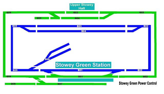
As can be seen, for ‘Cab Control’ there are 6 track sections on the blue circuit inner (lower) loop – B01 to B06
and 8 track sections on the green outer loop G01 – G08.
Point Control
Stowy Green’s points will be powered using Hornby Point motors recycled from the original Burton Crumpnold layout. As I am not planning to fit them directly to the points the difference in design between these and Peco point motors should not be an issue.
The Control panel will use a Capacitor Discharge unit. All of the points motors will be screwed to the main or upper station board using extension pins to operate the points.
The following diagram shows the point control.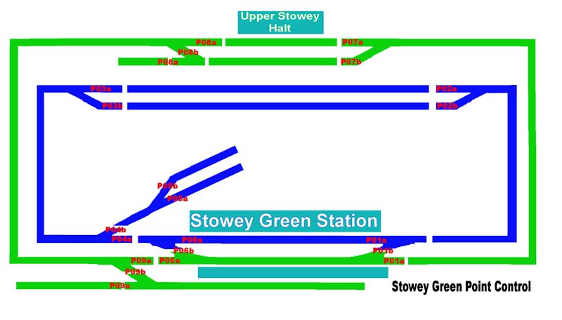
As you can see there are a total of 9 point operations, 4 of these P01, P06, P08 and P09 will be wired to operate a pair of points.
Wiring it All Up
Here is the underside of Stowey Green’s baseboard the board ready to be wired to the point and power plugs.
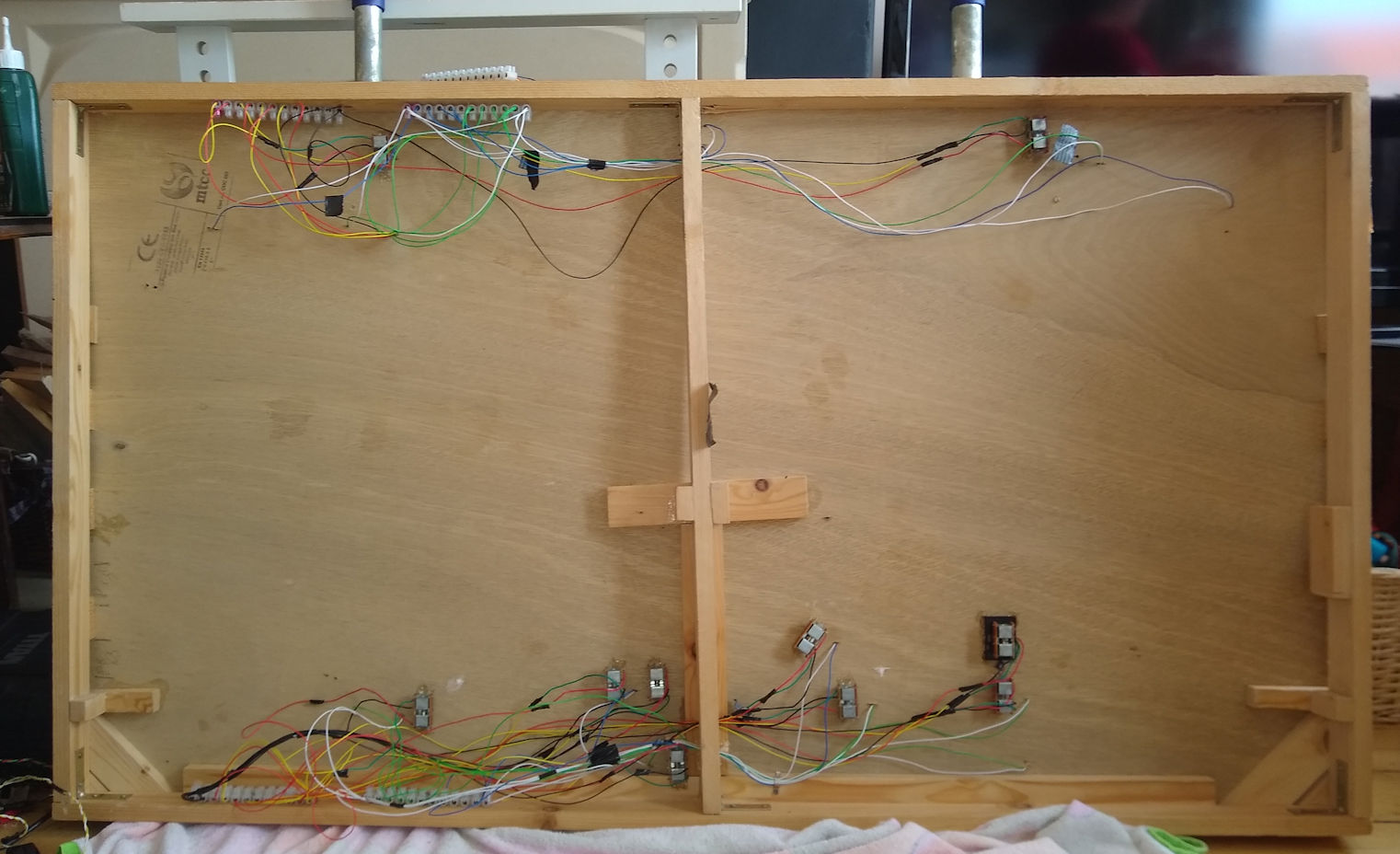
This picture clearly shows the 4 terminal blocks used to feed the power and points
Power cabling is Blue and Green with white as the common returns..
Point cabling is Yellow and Red with Black as the common
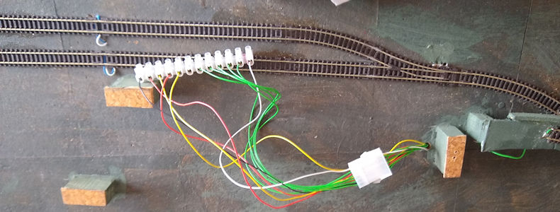
Just visible on top is the terminal strip that will feed the Upper Stowey board.
This terminal strip is connected to the main wiring using a ‘VAL-U-Lok’ 12 way connector as shown below.
This will allow the upper board to be disconnected as required
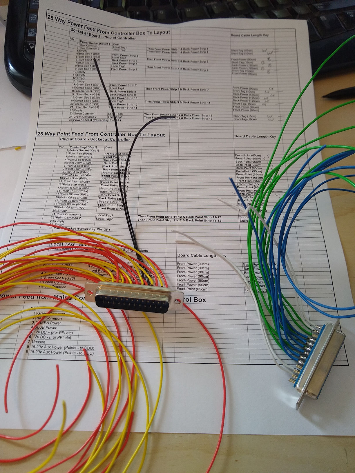
Here are the 25 way plug and socket ready to be attached to the main board. I have made extensive use of spreadsheets to ensure everything is wired correctly.
So finally here is the wired up underside of the Stowey Green board with the power and point control plugs and sockets wired in.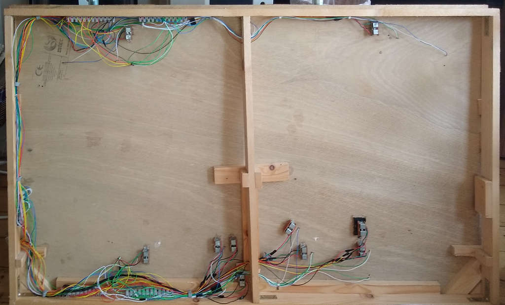
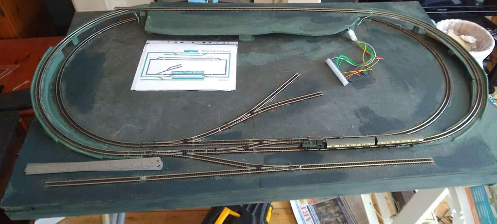
This is the view from the top with the connections for the removeable upper section ready to be connected to the track and points when they are laid.
The Control Panel Box
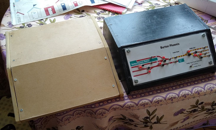
This is the new ‘bare’ Stowey Green control panel box. It is next to the Burton Phoenix control box it is based on.
The Stowey Green control panel has space for a larger panel and more room for the Gaugemaster controller on top.
The control panel has been be painted white using left over paint for when we do a bit more touching up the woodwork in the house.
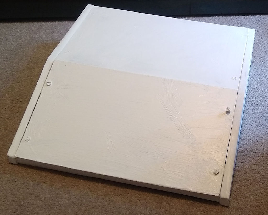
I promise the control box will look a lot better when the ‘Mimic Diagram’ and switches have been added.
Go onto how Stowey Green, once wired up with be finished off.